
Turntable Items
Upgrade Your Analog Playback System

The Cardas Myrtle Heart and Myrtle Silver Heart are highly evolved cartridges built on a unique Benz chassis. A well seasoned Cardas cartridge performs well at a high input impedance of 47k on a quiet system. A lower impedance of 500-1.5k works if the system tends to hum or the cartridge is not broken-in. These cartridges have a standard output of 0.3mV.
Specifications:
Body: Machined Vented Myrtlewood
Cantilever: Solid Boron rod, 0.28 mm diameter
Stylus: Nude line-contact diamond, mirror polished
Stylus Tip Radius: 5x 120 um
Vertical Tracking Angle: 20-22 degrees
Coil: Square Ruby jewel plate, Copper wire or Silver wire
Weight: 9.1 grams (copper), 9.5 grams (silver)
Output Voltage: 0.3 mV @ 3.54 cm/s
Internal Impedance: 45 ohms (copper), 30 ohms (silver)
Frequency Response: 10-50,000 Hz + 1 dB
Channel Balance: Better than 0.5 dB
Channel Separation: Better than 35 dB @ 1 kHz
Tracking Ability @ 315 Hz with a tracking force of 2 grams: >80um
Dynamic Compliance: 15 um/mN
Recommended Loading: 500-47.000 ohms
Optimum Tracking Force: 1.8-2.0 grams
Recommended Tone arm Mass: Medium to high
Recommended Break-in period: 40 hours
Part numbers:
P31.7 for Copper wound
P31.8 for Silver wound

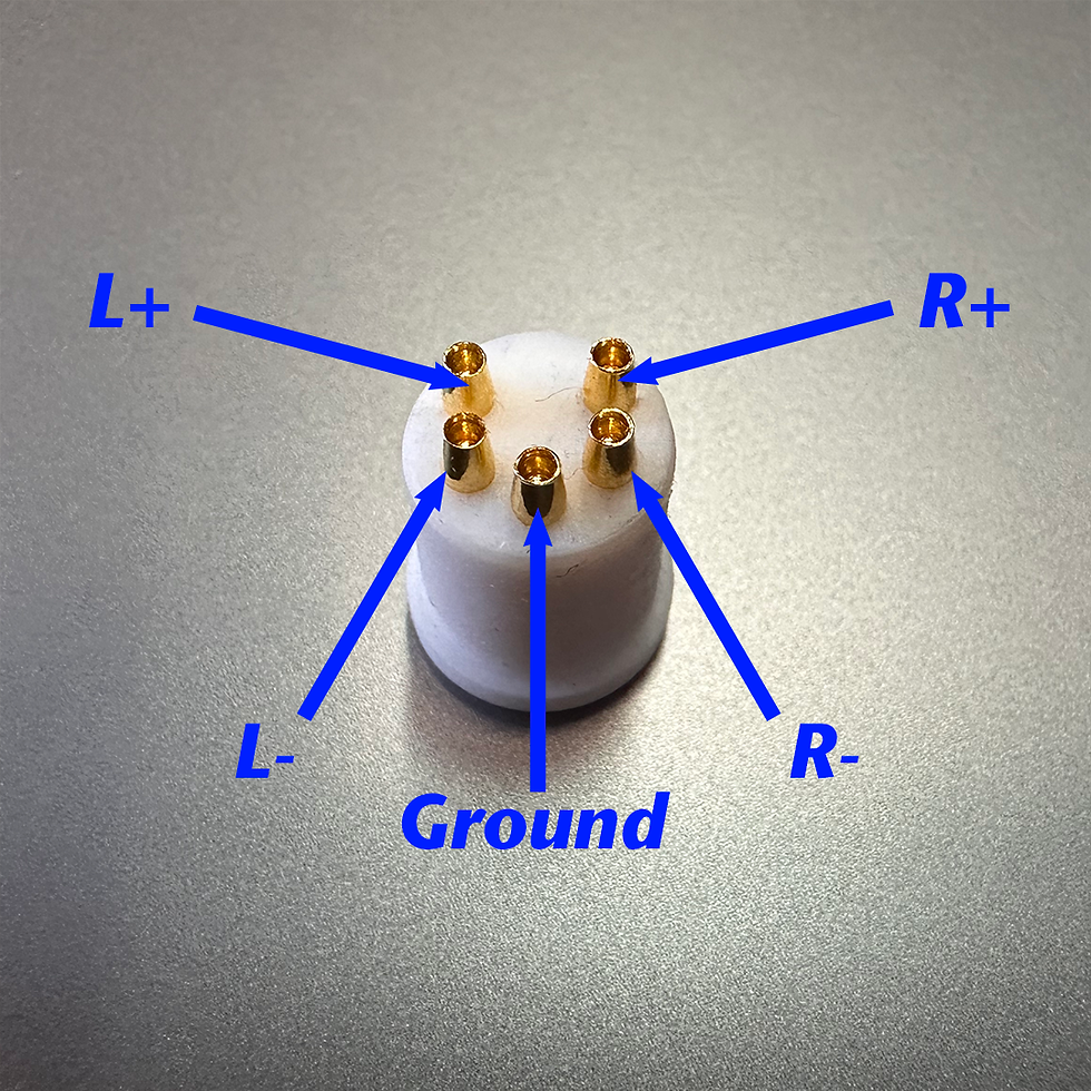
Cardas Audio offers 6 different DIN connectors. DIN connectors are sold as an OEM/DIY part, and are also terminated onto the source-end of our phono cables and phono boxes.
All of our DIN connectors feature gold plated brass contact surfaces, mounted in white Delrin.
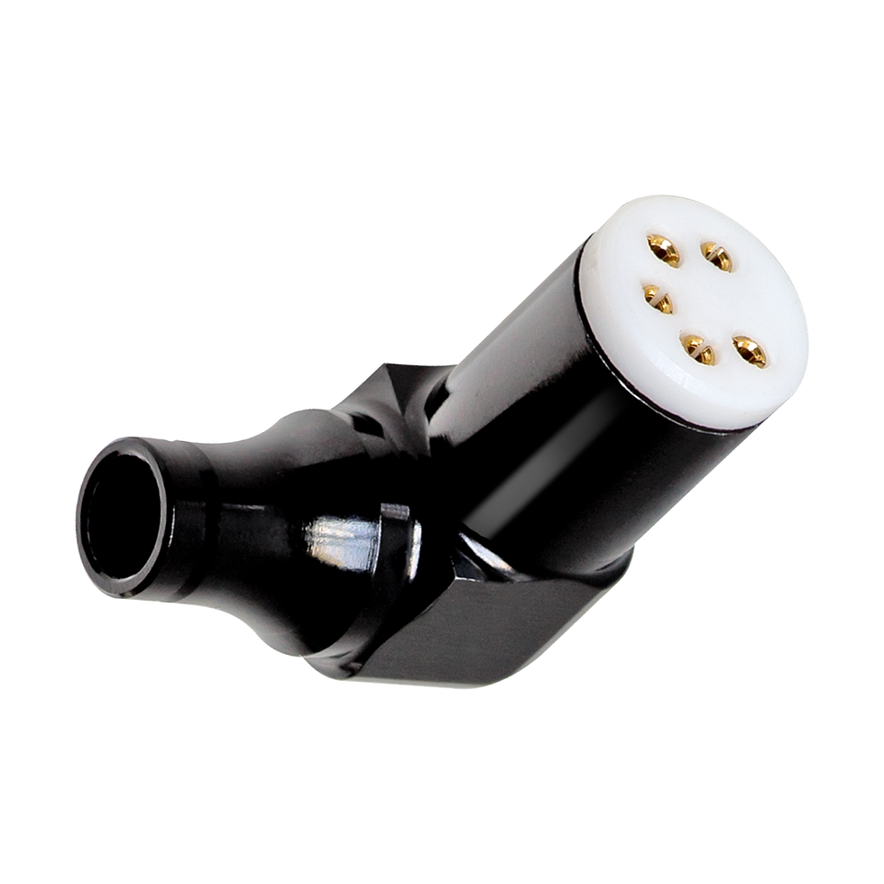
Our premium S-DIN (straight) and R-DIN (right-angle) have black anodized aluminum housings. Our economy model S-DIN-E has a black Delrin outer barrel. The DIN portion in all 3 models can be rotated to any orientation.
The DIN connector alone can be purchased as the TIDP.
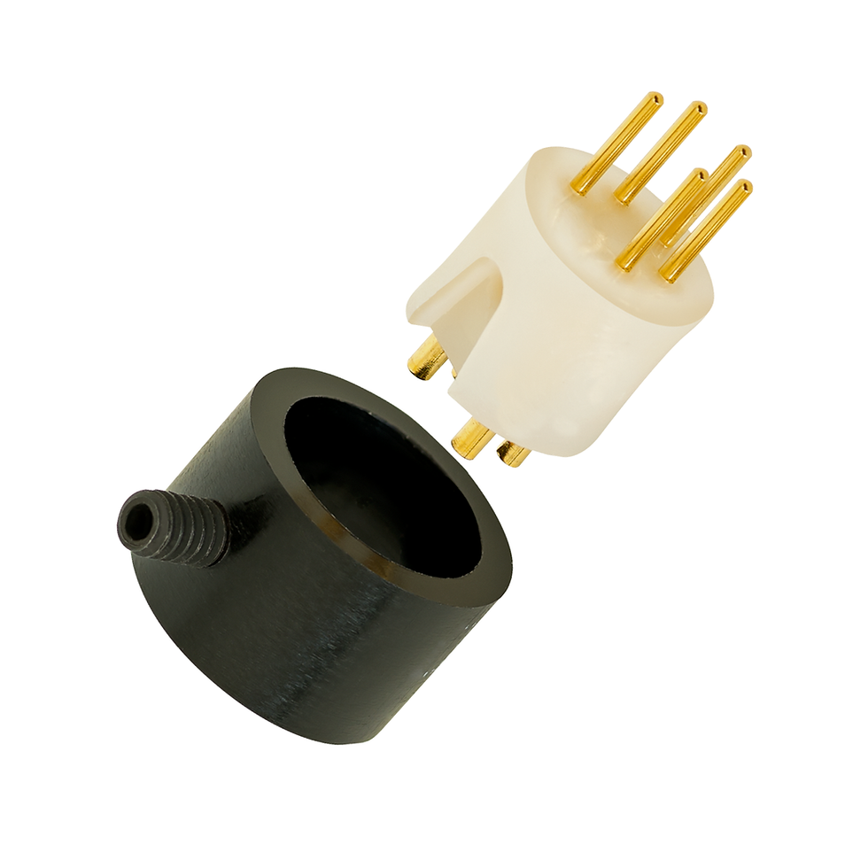
Our male DIN connectors include the M-DIN, and the M-DIN-R for Rega tonearms.
Part numbers:
P34.13 for S-DIN (Straight DIN)
P34.14 for R-DIN (Right Angle DIN)
P34.17 for S-DIN-E (Economy Straight DIN)
P34.12 for TIDP (Female w/o body)
P34.3 for M-DIN (Male DIN w/o body)
P34.16 for M-DIN-R (Male DIN with Rega sleeve)
P34.14
P34.16

Aluminum housing, black anodized with Cardas logo engraved on the top. Cardas 4x24 With Shield internal wire and Cardas solder. Cardas DIN on a 12” flexible lead that won’t interfere with suspended tables. Dual female RCA outputs and ground screws. This box allows the use of standard interconnects with your high performance analog rig.
Part numbers:
P31.25 for CPTB ST (box with straight DIN)
P31.24 for CPTB RT (box with right-angle DIN)
P31.22 for CPIB (DIY "make your own" phono box)

P31.24

P31.25

P31.22
P31.24

Description: Set of four 1.5” long headshell leads made with our standard 33 AWG or top-of-the-line Clear 34 AWG tonearm wire. Factory terminated with Cardas PCC ER (silver/rhodium) or PCC ER (gold plated) cartridge clips.
Part numbers:
P31.44 for Clear 34 AWG Headshell Leads
P31.16 for 33 AWG PCC ER Headshell Leads
P31.15 for 33 AWG PCC EG Headshell Leads

24”/60.96cm long 33x4 or our flagship Clear 34x4 tonearm wires factory terminated with Cardas PCC ER at one end and tinned with Cardas solder at the other so it can easily be terminated to whatever you need.
For more information about Cardas tonearm wire, click here.
Termination: PCC ER to tinned leads
Part numbers:
P31.40 for Clear 34 AWG Tonearm Leads
P31.34 for 33 AWG Tonearm Leads

P31.18

P31.27
P31.18
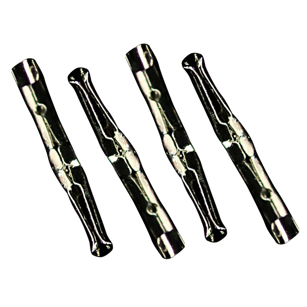
Set of four cartridge clips. Fits most cartridge pins and tonearm pins (1mm and 1.2mm). Solderable end with flexible tip to grip pins.
Base metal: High copper content brass
Plating: Silver/rhodium (PCC ER) or gold (PCC EG)
Termination: Solder
Part numbers:
P31.18 for PCC ER (Silver/Rhodium plated)
P31.27 for PCC EG (Gold plated)

It's expensive and it's a pain to work with. Let's get that out of the way first.
But this is our highest performing tonearm wire. Neutral and transparent, with holographic imaging. We believe our 34 AWG tonearm wire is the finest available anywhere.
For more information about Cardas tonearm wire, click here.
Instead of a rubber or PVC jacket, this wire has a "served" jacket, which is a twist of microfibers surrounding the copper conductor. Preparing this wire requires a special technique which is detailed in the video below. We highly recommend that you watch it first.
Part number:
C9.27

Description: Multi-stranded tonearm wire, in a braid of four 33 AWG multi stranded conductors. A nice upgrade for any tonearm.
For more information about Cardas tonearm wire, click here.
Part number:
C9.18